Last updated: (05-01-2017)
I enjoy brewing my own beer and I have had this idea for a project kicking around for quite a while to make the plans for a mostly automated brewing system like the pico brew but using industrial automation and 5-15gallon batch. Unfortunately at this stage in my life I will not be able to go beyond planning and specifications, due to lack of space and funds so lets call it a thought experiment for the time being. (note: some of the documents are linked at the end)
So the Idea is this:
- a 3 pot/vessel system first the HLT (hot liquor tun), the Mash tun, and finally the boil kettle.
- all liquid movement and temperature will be controlled by PLC which will send data to temperature PID controllers via Modbus
- temperatures and time will be set at an HMI
- tanks will begin heating once heating element is submerged to reduce dead time.
- grain and hops will be added manually mostly to reduce some complexity (haha… ok might be a later project)
- there will be full manual control as well (jog switch)
- all pipes will be connected with cam lock fittings (this may change)
To Do List:
- front panel layout(currently hand drawn)
- internal panel layout
- control power supply sizing
- BOM’s (90% complete)
- IO sheet (partially complete; need PLC selected for finalization)
- programing
- HMI design
- pressure transmitter selection
General brewing process:
- Sanitize everything
- fill the hot water tank
- heat the tank to striking temperature 160-180F (depending on the mash temperature you require 150F-168F and grain temp)
- fill mash tun with grains
- slowly transfer the hot liquid to the mash tun (doing it slowly prevents dough balls from forming that and stirring)
- refill the HLT and heat it to your mash temperature
- recirculate the wert through a heat exchanger coil in the HLT (see the PFD)
- let the tank recirculate for about an hour-90 minutes to convert as much of the starch as possible to sugars
- begin transferring wort to the kettle
- transfer the HLT sparge water to the mash tun as the mash tun is very slowly transferring to the boil kettle
- once complete bring the kettle to a boil for 60-90 minutes (depends on recipe)
- add your hops at recipe specified intervals (for bittering and flavoring) and other additives (Irish moss, sugars, spices, etc.)
- recirculate the cooked wert through a heat exchanger to cool it down to ~70F
- oxygenate the wert since boiling brings the dissolved oxygen to 0 ppm yeast needs it for early stage fermentation
- transfer to fermentation vessel like a carboy and add yeast.
- clean and sanitize everything (except the HLT)
Planing Documentation:
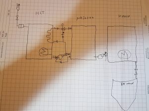
First my HandCAD™ PFD.
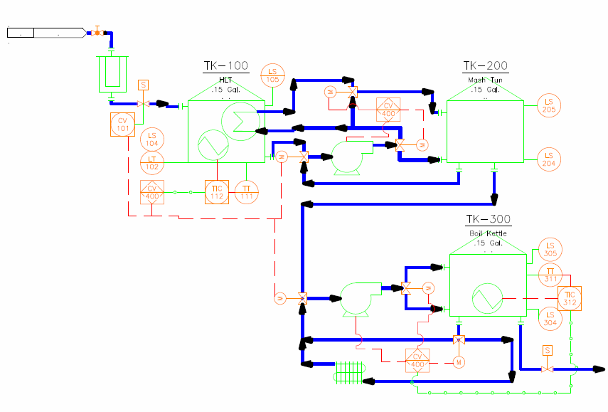
and my more detailed P&ID:
note: I am missing the hand shutoff valves that will be attached at each flange.
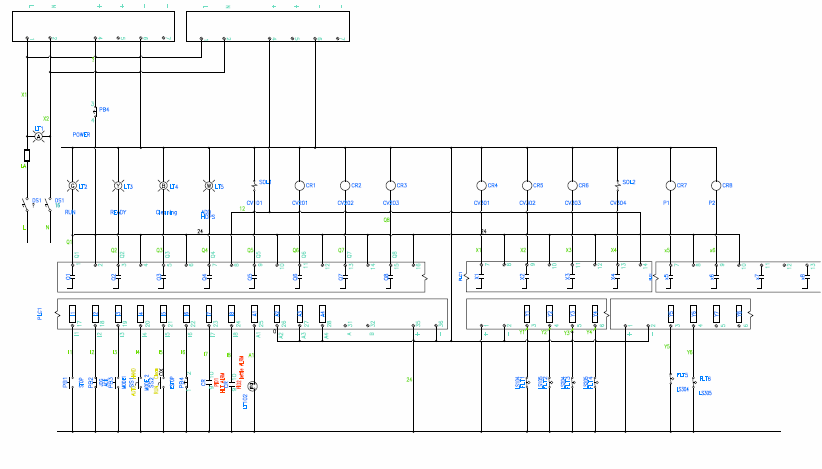
PLC Wiring Diagram:
my IO sheet:
| Inputs | ||||
| name | description | type | PLC register | note |
| SS1 | run/clean mode | D | I01 | |
| SS2 | Auto/man | D | I02 | |
| PB1 | Start | D | I03 | |
| PB2 | stop | D | I04 | |
| PB3 | jog/ack | D | I05 | |
| Estop | D | I06 | ||
| TC1 | pd540 alrm (HLT) | D | I07 | |
| TC2 | pd540 alrm (kettle) | D | I08 | |
| LS104 | level float switch | D | y01 | |
| LS105 | level float switch | D | y02 | |
| LS204 | level float switch | D | y03 | |
| LS205 | level float switch | D | y04 | |
| LS304 | level float switch | D | y05 | |
| LS305 | level float switch | D | y06 | |
| LT121 | HLT level transmitter | A/4-20 | A1 | 0-1bar |
| LT221 | Mash level transmitter | A/4-20 | A2 | 0-1bar |
| Outputs | ||||
| Name | Description | direct/ relay | PLC register | note |
| PL2 | Run | d | Q1 | green |
| PL3 | ready | d | Q2 | yellow |
| PL4 | clean | d | Q3 | blue |
| PL5 | hops addition | d | Q4 | White (flashing) |
| CV101 | input solenoid | d | Q5 | 1/2″npt |
| cv201 | tank selector | r | Q6 | 1/2″npt |
| cv202 | mash/ recerc select | r | Q7 | 1/2″npt |
| cv203 | hlt/direct | r | Q8 | 1/2″npt |
| cv301 | from mash/kettle | r | x1 | 1/2″npt |
| cv302 | fill/recerc | r | x2 | 1/2″npt |
| cv303 | recerc/chill | r | x3 | 1/2″npt |
| cv304 | drain solenoid | d | x4 | 1/2″npt |
| pmp1 | HLT/mash | r | x5 | 7gpm CPSS-IN-1 |
| pmp2 | mash/kettle | r | x6 | 7gpm CPSS-IN-1 |
Hardware selection (update):
Complete brew hardware BOM (everything directly attached to the tanks)
At this point I have selected most of my control hardware.
(note the following section is out of date)
F̶i̶r̶s̶t̶ ̶o̶f̶f̶ ̶w̶e̶r̶e̶ ̶m̶y̶ ̶t̶e̶m̶p̶e̶r̶a̶t̶u̶r̶e̶ ̶c̶o̶n̶t̶r̶o̶l̶l̶e̶r̶s̶ ̶w̶h̶i̶c̶h̶ ̶a̶r̶e̶ ̶P̶D̶5̶4̶0̶’̶s̶.̶ ̶ ̶F̶i̶r̶s̶t̶ ̶b̶e̶c̶a̶u̶s̶e̶ ̶I̶ ̶h̶a̶v̶e̶ ̶e̶x̶p̶e̶r̶i̶e̶n̶c̶e̶ ̶u̶s̶i̶n̶g̶ ̶t̶h̶e̶m̶,̶ ̶s̶e̶c̶o̶n̶d̶ ̶t̶h̶e̶y̶ ̶h̶a̶v̶e̶ ̶p̶r̶o̶v̶e̶n̶ ̶t̶o̶ ̶b̶e̶ ̶v̶e̶r̶y̶ ̶v̶e̶r̶s̶a̶t̶i̶l̶e̶ ̶a̶n̶d̶ ̶h̶a̶v̶e̶ ̶a̶ ̶g̶o̶o̶d̶ ̶f̶e̶a̶t̶u̶r̶e̶ ̶s̶e̶t̶.̶ ̶T̶h̶i̶r̶d̶ ̶t̶h̶e̶y̶ ̶h̶a̶v̶e̶ ̶ ̶R̶S̶4̶8̶5̶ ̶w̶i̶t̶h̶ ̶M̶o̶d̶u̶s̶ ̶A̶S̶C̶I̶I̶/̶R̶T̶U̶ ̶s̶u̶p̶p̶o̶r̶t̶ ̶w̶h̶i̶c̶h̶ ̶w̶i̶l̶l̶ ̶b̶e̶c̶o̶m̶e̶ ̶ ̶n̶e̶c̶e̶s̶s̶a̶r̶y̶ ̶f̶o̶r̶ ̶u̶s̶a̶g̶e̶ ̶v̶e̶r̶s̶a̶t̶i̶l̶i̶t̶y̶ ̶w̶i̶t̶h̶ ̶a̶ ̶H̶M̶I̶ ̶l̶a̶t̶e̶r̶.̶ ̶I̶t̶ ̶w̶i̶l̶l̶ ̶c̶o̶n̶t̶r̶o̶l̶ ̶ ̶2̶4̶0̶V̶ ̶i̶m̶m̶e̶r̶s̶i̶o̶n̶ ̶ ̶h̶e̶a̶t̶e̶r̶s̶ ̶a̶n̶d̶ ̶e̶i̶t̶h̶e̶r̶ ̶a̶ ̶t̶h̶e̶r̶m̶a̶l̶ ̶c̶o̶u̶p̶l̶e̶ ̶o̶r̶ ̶R̶T̶D̶ ̶f̶e̶e̶d̶b̶a̶c̶k̶
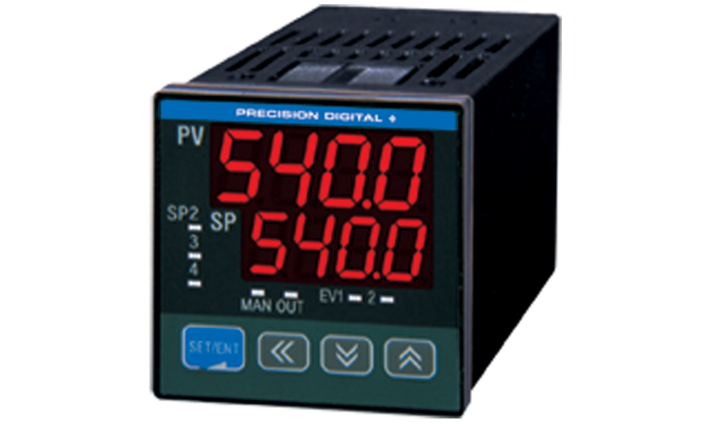

Next were my motorized control valves which I managed to find a 10pack of 1/2″ NPT 3-way T valves I need 6 but hey 4 spares for other projects can’t hurt.

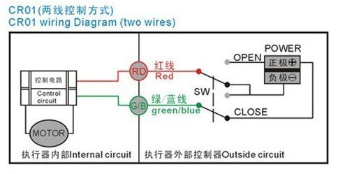
Food grade stainless should be used for this but since price is an object and $100+ per valve before shipping is a little out of budget so brass body and stainless ball it is. Each valve will be controlled via a DPDT din-mounted relay so PLC outputs can be conserved.
The transfer pumps are going to be 2 of these chugger 7gpm @4 ft of head centrifugal pumps they are rated food safe at 250F which should be just fine since I should mostly be working with sub 212F liquids and considering initially I will only be working with 15 Gal and less, 7gpm will mostly be too much so I will be throttling the flow rate with hand valves(which is why I chose a centrifugal pump) one of the benefits is they are magnetically coupled so bearing seals wont be a concern if it gets run dry.

as for my shutoff solenoid valves I will most likely use these 12v valves no special reason other than they should fit the need

I also haven’t decided on how I will be measuring liquid levels but I am leaning towards a low pressure transmitter since my tanks will most likely be around 20″ tall so that equates to ~0.8 psi or ~ 58mbar
I have partially written the ladder logic in Teco’s LAD IDE just to get a feel for it since my prior experience revolves around the old Siemens simatic S7 IDE and RSlogix (I do miss some of the features that the S7 logic blocks provided).
PLC wire diagram-Layout1 P&ID-PID ANSI D Title Block BREW IO and BOM


